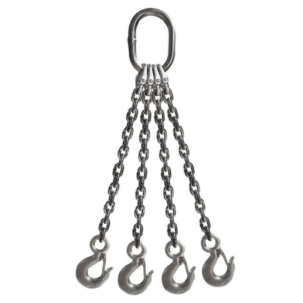
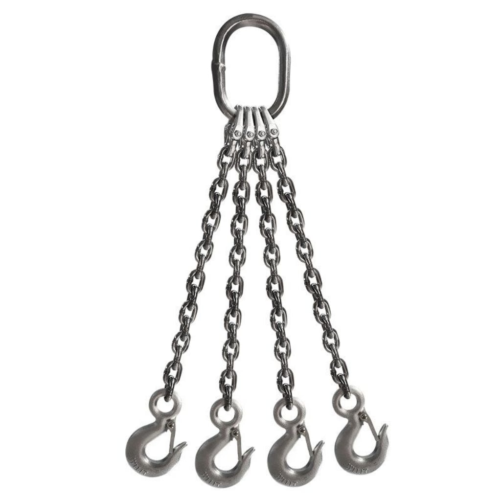
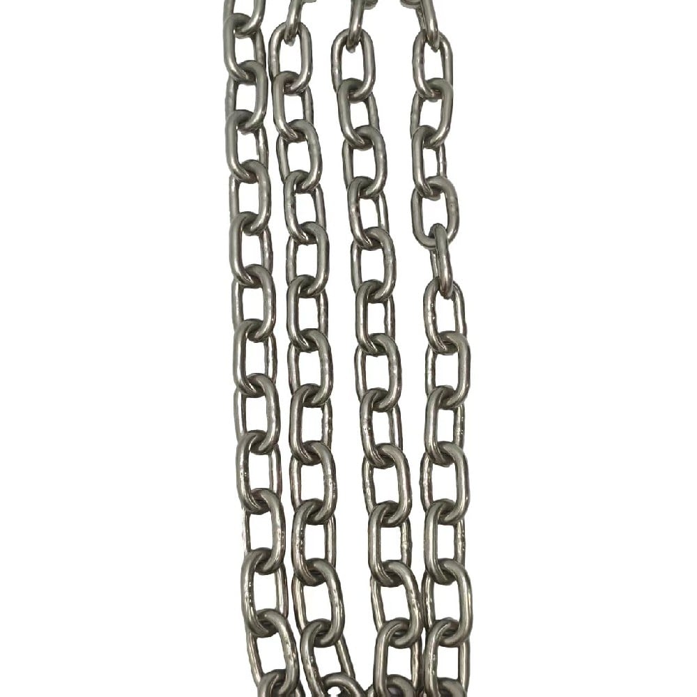
G80 Stainless Steel Chain Sling is manufactured from Grade 80 stainless steel lifting chain and assembled with stainless steel master links, hooks and connecting components. Available in single leg, double leg, three leg and four leg configurations, it is designed for lifting applications requiring corrosion resistance and Grade 80 load capacity. It is widely used in marine, offshore, food processing, chemical and industrial lifting environments.
G80 Stainless Steel Chain Sling is a lifting assembly consisting of Grade 80 stainless steel chain and compatible lifting components. The sling configuration can be customized according to lifting requirements, including leg number, chain diameter, effective working length and end fittings.
Compared with conventional alloy steel Grade 80 chain slings, stainless steel G80 chain slings are selected for applications where corrosion resistance and surface cleanliness are required.
Product Structure
Available configurations:
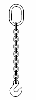
Single Leg Chain Sling
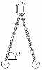
Two Leg Chain Sling
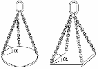
Three Leg Chain Sling
Four Leg Chain Sling
Main components:
Grade 80 Stainless Steel Chain
Master Link
Connecting Link
Clevis Hook
Self-Locking Hook
Shortening Device
Working Conditions
The Working Load Limit (WLL) must not be exceeded during lifting operations.
The chain sling must be selected according to:
Load weight
Chain diameter
Number of loaded legs
Sling angle
Working environment
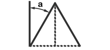
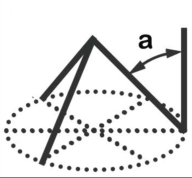
Multi-leg chain slings require correct angle selection because the load on each leg increases as the angle becomes larger.
Application Environment
G80 Stainless Steel Chain Sling is suitable for:
Marine lifting operations
Offshore maintenance
Food processing equipment handling
Chemical industry applications
Clean manufacturing environments
Corrosion-sensitive industrial lifting
Parameter
Meter table
Diameter of Lifting Chain
1 Leg
2 Legs
3 & 4 Legs
Continuous Sling
0<a<45°
45°<a<60°
0<a<45°
45°<a<60°
Factor 1.0
Factor 1.4
Factor 1.0
Factor 2.1
Factor 1.5
Factor 1.6
(mm)
(ton)
(ton)
(ton)
(ton)
(ton)
(ton)
4
0.5
0.71
0.5
1.06
0.75
0.8
5
0.8
1.12
0.8
1.6
1.18
1.24
6
1.12
1.6
1.12
2.36
1.7
1.8
7
1.5
2.12
1.5
3.15
2.24
2.5
8
2
2.8
2
4.25
3
3.15
10
3.15
4.25
3.15
6.7
4.75
5
13
5.3
7.5
5.3
11.2
8
8.5
16
8
11.2
8
17
11.8
12.5
18
10
14
10
21
15
16
19
11.2
16
11.2
23.5
16.8
17.9
20
12.5
17
12.5
26.2
18.7
20
22
15
21.2
15
31.5
22.5
24
26
21.2
30
21.2
44.5
31.8
33.9
28
25
33.5
25
52.5
37.5
40
30
28
39.2
28
58.8
42
44.8
32
31.5
45
31.5
66.1
47.2
50.4
36
40
56
40
84
60
64
38
45
63
45
94.5
67.5
72
40
50
70
50
105
75
80
45
63
88.2
63
132.3
94.5
100.8
50
78.5
109.9
78.5
164.8
117.7
125.6
Continuous Sling
Working Load Limit (WLL) for an endless chain sling configuration.
0° < a < 45° The angle between the sling leg and the vertical is between 0° and 45°.
45° < a < 60° The angle between the sling leg and the vertical is between 45° and 60°.
Factor The load multiplier used to calculate the Working Load Limit for different sling configurations and lifting angles.
a The angle between the sling leg and the vertical line.
(ton) All values are expressed in metric tons and represent the maximum Working Load Limit (WLL).
Feet table
Design Factor
1-Leg Sling
2-Leg Sling
3-Leg & 4-Leg Slings
4:01
Chain Diameter
90 Degrees
60 Degrees
45 Degrees
30 Degrees
60 Degrees
45 Degrees
30 Degrees
Load Factor: 1
Load Factor: 1.7
Load Factor: 1.4
Load Factor: 1
Load Factor: 2.6
Load Factor: 2.1
Load Factor: 1.45
7/32″
2,100
3,600
3,000
2,100
5,500
4,400
3,200
9/32″
3,500
6,100
4,900
3,500
9,100
7,400
5,200
5/16″
4,500
7,800
6,400
4,500
11,700
9,500
6,800
3/8″
7,100
12,300
10,000
7,100
18,400
15,100
10,600
1/2″
12,000
20,800
17,000
12,000
31,200
25,500
18,000
5/8″
18,100
31,300
25,600
18,100
47,000
38,400
27,100
3/4″
28,300
49,000
40,000
28,300
73,500
60,000
42,400
7/8″
34,200
59,200
48,400
34,200
88,900
72,500
51,300
1″
47,700
82,600
67,400
47,700
123,900
101,200
71,500
1-1/4″
72,300
125,200
102,200
72,300
187,800
153,400
108,500
Design Factor 4:1 The minimum breaking force of the sling assembly is at least 4 times its Working Load Limit (WLL).
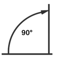
90 Degrees
The sling is lifting vertically with no sling angle reduction.
60 Degrees / 45 Degrees / 30 Degrees
The angle between each sling leg and the horizontal plane. As the angle decreases, the sling capacity decreases.
Load Factor
A multiplier used to calculate the Working Load Limit based on the number of sling legs and the lifting angle.
WLL Values (lbs) The numbers shown in the table represent the maximum Working Load Limit in pounds for each chain diameter and sling configuration.
Example: For a 1/2" chain sling:
1-Leg Sling = 12,000 lbs
2-Leg Sling at 60° = 20,800 lbs
2-Leg Sling at 45° = 17,000 lbs
2-Leg Sling at 30° = 12,000 lbs
3 & 4-Leg Sling at 60° = 31,200 lbs
3 & 4-Leg Sling at 45° = 25,500 lbs
3 & 4-Leg Sling at 30° = 18,000 lbs
Note: The lifting angle shown in this table is measured from the horizontal. Smaller angles result in higher tension in each sling leg and lower overall lifting capacity.
Standards
Name
G80 Stainless Steel Chain Sling
MOQ
1 Piece
Package
Carton + Steel Pallet
Manufacturing Standards
G80 Stainless Steel Chain Sling is manufactured using Grade 80 stainless steel lifting chain and compatible lifting components.
Applicable standards include:
EN 818-2 Lifting chain for chain slings
EN 818-4 Chain slings — Safety requirements
EN 1677 Components for slings
ISO 1834 Short link lifting chain requirements
The assembled sling is marked with:
Working Load Limit (WLL)
Chain diameter
Identification information
Manufacturer traceability
Testing Standards
Each G80 Stainless Steel Chain Sling is inspected before delivery, including:
Material verification
Chain dimension inspection
Component inspection
Welding and connection inspection
Proof load testing
WLL verification
Identification marking inspection
Test certificates and traceability documents are available according to customer requirements.
Application Standards
G80 Stainless Steel Chain Sling is designed for lifting applications including:
Marine equipment lifting
Offshore maintenance operations
Chemical equipment handling
Food processing machinery installation
Industrial material handling
During operation:
Do not exceed the marked WLL.
Avoid shock loading and sudden impact loads.
Do not use damaged or deformed chain components.
Hooks should be loaded at the hook saddle position.
Multi-leg sling angles must be controlled according to lifting requirements.
Maintenance Standards
Regular inspection should include:
Chain link wear
Chain deformation
Corrosion condition
Hook opening deformation
Master link damage
Identification marking condition
Remove the sling from service when:
Chain links show cracks or permanent deformation
Excessive wear reduces the original dimensions
Hooks are damaged or excessively opened
Components cannot maintain the rated load capacity